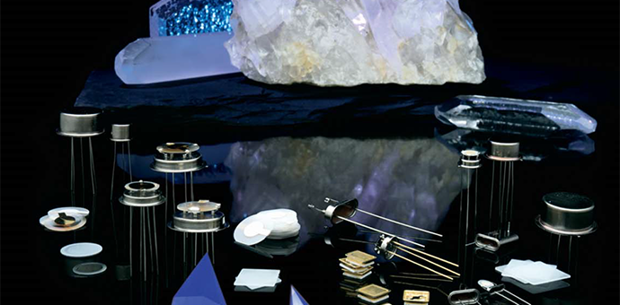
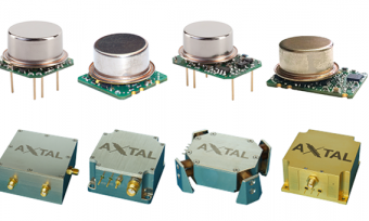
Quartz crystal resonators:
Doubly rotated crystal selection:
| The choice of which doubly rotated crystal cut to use is dependent upon a number of factors including the desired operating temperature.
FC-cut, IT-cut and SC-cut crystals have widely different lower and upper turning point temperatures and therefore the choice of crystal cut and oven temperature should be closely coordinated. |
Type of cut | Turn point | Typical turning point |
| FC | Upper | +55°C to +75°C | |
| IT | Upper | +85°C to +105°C | |
| SC | Lower | +60°C to +80°C | |
| SCM1 | Lower | +65°C to +85°C | |
| SCM2 | Lower | +85°C to +100°C |
See before table for ordering information:
Note that the nine digit CRYSTAL CODE addresses only the six parameters outlined above. Unless otherwise specified by the customer, the values of any additional parameters will be per the latest revision of MIL-PRF-3098.
If the crystal requirements cannot be fully described by the nine digit code, a unique deviation number will be assigned by the factory
| MODE | HOLDER | CAL. TOL. | TEMPERATURE STABILITY
OR TOTAL TOLERANCE |
OPERATING TEMP. | CIRCUIT CONDITION | ||||||||
| Code | Desc. | Code | Desc. | Code | Desc. | Code | Desc. | Code | Desc. | Code | Desc. | Code | Desc. |
| A | Fund. | 35 | HC-35/U | 0 | Standard | X | +/-1.5ppm | X | +/-2ppm stability | X | +15ºC to +35ºC | 00 | Series resonance |
| B | 3rd | 36 | HC-36/U | 1 | Surface mount | A | +/-2ppm | Y | +/-3ppm stability | Y | +10ºC to +40ºC | 01 | Parallel resonance load capacity of 100pF or more Advise actual value |
| C | 5th | 37 | HC-37/U | 2 | Surface mount | B | +/-5ppm | Z | +/-4ppm stability | Z | +5ºC to +45ºC | ||
| D | 7th | 40 | HC-40/U | 3 | Slimline | C | +/-7ppm | B | +/-5ppm stability | A | +0ºC to +50ºC | ||
| E | 9th | 42 | HC-42/U | 4 | Modified can height | D | +/-10ppm | C | +/-7ppm stability | B | -5ºC to +55ºC | 10 to 90 | Parallel resonance load capacity in pF |
| F | 11th | 43 | HC-43/U | 5 | Modified can height | E | +/-15ppm | D | +/-10ppm stability | D | -10ºC to +60ºC | ||
| 45 | HC-45/U | 6 | Modified can height | F | +/-20ppm | E | +/-15ppm stability | E | -15ºC to +65ºC | 99 | Calibration at reference temperature in customer’s oscillator | ||
| 47 | HC-47/U | 7 | Four point mount | G | +/-25ppm | F | +/-20ppm stability | F | -20ºC to +70ºC | ||||
| 48 | HC-48/U | 8 | Modified can height | H | +/-30ppm | G | +/-25ppm stability | G | -25ºC to +75ºC | ||||
| 49 | HC-49/U | 9 | Modified can height | J | +/-40ppm | H | +/-30ppm stability | H | -30ºC to +80ºC | ||||
| 50 | HC-50/U | M | +/-50ppm | J | +/-40ppm stability | J | -40ºC to +90ºC | ||||||
| 51 | HC-51/U | K | +/-100ppm | M | +/-50ppm stability | M | -55ºC to +105ºC | ||||||
| 52 | HC-52/U | L | +/-70ppm stability | U | +50ºC to +60ºC oven | ||||||||
| 90 | SM1 | K | +/-100ppm stability | L | +55ºC to +65ºC oven | ||||||||
| N | +/-150ppm stability | T | +60ºC to +70ºC oven | ||||||||||
| S | Specific curve | N | +65ºC to +75ºC oven | ||||||||||
| T | +/-20ppm (4) (B)* | P | +70ºC to +80ºC oven | ||||||||||
| U | +/-25ppm (4) (C)* | R | +75ºC to +85ºC oven | ||||||||||
| V | +/-30ppm (4) (D)* | S | +80ºC to +90ºC oven | ||||||||||
| W | +/-50ppm (4) (F)* | V | +85ºC to +95ºC oven | ||||||||||
| P | +/-100ppm (4) (H)* | W | +90ºC to +100ºC oven | ||||||||||
| R | +/-200ppm (4) (M)* | C | +95ºC to +105ºC oven | ||||||||||
| 0 | Turn over point in oven range | 0 | Not specified | ||||||||||
| *Corresponding calibration codes | |||||||||||||
Eg. A357DFE-32 @ 20M is translated as follows:
A = Fundamental mode of operation
35 = HC-35/U holder
7 = Four point mount for improved g-sensitivity
D = Calibration tolerance of +/-10ppm at the reference temperature
F = Temperature stability of +/-20 ppm, with respect to the frequency measured at the reference temperature
E = Temperature range of -15°C to +65°C, over which the temperature stability is effective
32 = When present, these two digits specify parallel resonance operation and the load capacitance in pF (i.e. 32pF)
20M = Nominal frequency of 20MHz


Reviews
There are no reviews yet.